Faraday’s laws of magnetic induction, foundational to many electrical and mechanical discoveries, have unveiled one of the most vital innovations in engineering – the induction motor. These laws reveal the profound connection between electricity and magnetism, leading to the creation of motors that power our world. In this exploration, we’ll delve into the inner workings of these remarkable machines, understanding how Faraday’s principles guide the operation of induction motors. So, let’s embark on this electrifying journey!
The stator is the main part of the motor. It obtains electricity and uses it to generate torque, which is a twisting force. Torque creates a magnetic field in another component of the motor known as the rotor. Because of magnetic attraction, the rotor creates a magnetic field and attempts to follow the stator. The slight speed difference between the stator and rotor is what causes electricity to flow.
To improve the performance, we placed wire coils on the magnet’s poles. These poles are sold in groups of two, four, or six. More pairings equals slower motor speed. As a result, the number of pole pairs determines how fast the motor runs. All of these components are attached to a central rod.
What exactly is an induction motor?
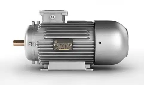
An induction motor is a type of electro-mechanical device that transforms electrical energy into mechanical energy. It is made up of two main parts: the stator and the rotor. The stator, as the name implies, remains stationary, whilst the rotor is the motor’s revolving component. Depending on their intended application, induction motors can be classified as single-phase or three-phase.
Induction motors have been around for almost a century, with Nikola Tesla being credited as the inventor of the first induction motor.
The Operation of Induction Motors
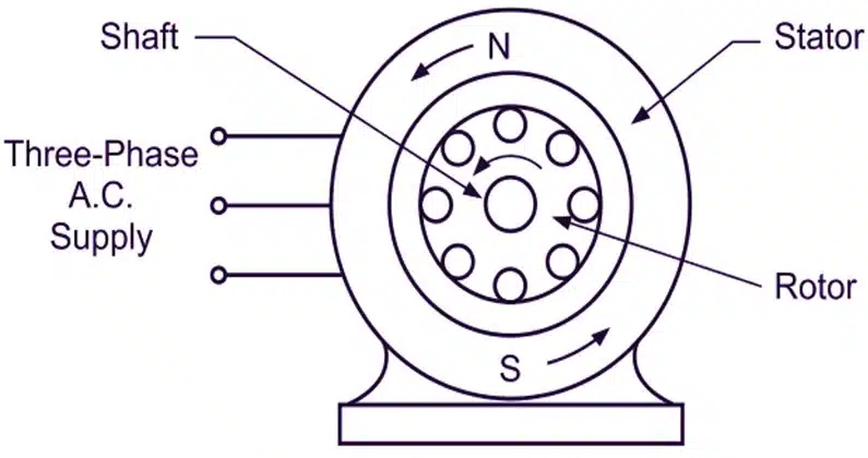
Induction motors, unlike DC motors, use only alternate current to power their stator windings. The alternating magnetic flux is generated by the AC current flowing through the stator windings. This magnetic flux has a cyclical pattern. The alternating magnetic flux creates an Electromagnetic Field (EMF) within the rotor conductors, which is critical in induction motors.
The generated EMF in the rotor conductors causes a current to flow in the rotor. This fundamental operation is what gives rise to the term “induction motors.” The induced current in the rotor conductors creates a magnetic field surrounding the rotor. This magnetic field, according to Lenz’s law, opposes the precise cause that created it.
There is a significant speed difference between the stator and the rotor, with the rotor attempting to maintain its rotation with that of the stator. As a result, both components try to spin in the same direction. The rotor, however, never achieves the exact same speed of the stator, providing the fundamental operating principle underlying all induction motors.
Components of an AC Motor
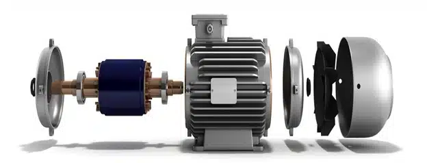
An AC motor is made up of several main components that work together to enable its operation:
Stator
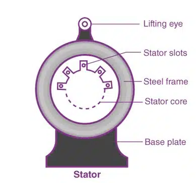
The stator is the stationary component of an alternating current motor. It is important in generating the magnetic flux directed toward the rotor. The stator core is outfitted with laminations that limit energy loss to improve energy efficiency. The stator is surrounded by winding, resulting in a hollow cylinder. These stator windings are linked to the alternating current power supply.
Rotor
The rotor is the dynamic element of the AC motor that moves it. It has a shaft on which it is mounted. When the stator generates a magnetic flux via the AC supply, the rotor induces a comparable magnetic flux. This induced flux causes torque to be generated within the rotor, causing it to revolve. As the rotor turns, an opposing current flows through the shaft.
Bearings
Bearings are circular components that support and maintain the shaft’s position. They are critical in decreasing friction between moving parts, which improves the overall efficiency of the AC motor. This reduction in friction not only increases efficiency but also contributes to the motor’s smooth and noiseless running.
Motor shaft
Engineers use a metal shaft to create the rotor assembly in an AC motor. They mount the rotor onto the shaft and extend the shaft beyond the motor casing. This extension allows the shaft to connect to external components and convert the motor’s rotational power into usable mechanical output.
Enclosures
A two-end bracket frame is used in which all motor parts are kept. This enclosure protects the internal parts of the AC motor from the external environment.
Induction Motor Types
AC induction motors are classified according to their working principles. There are two main kinds:
- Synchronous Motor
- The Induction Motor
The induction motor, in turn, can be classified into two kinds based on the source of AC power:
- Induction Motor with One Phase
- Induction three-phase motor
Synchronous Motor
Synchronous motors get its name from the fact that they run at a constant, synchronous pace. This means that the electromagnetic force generated by these motors is constant. Synchronous motors, in essence, always run at a constant speed.
In a synchronous motor, a DC source supplies the rotor, while a three-phase AC supply energizes the stator. The stator winding generates a stable magnetic flux, and the DC supply connected to the rotor creates a continuous flux. To start the motor, we apply mechanical power to the rotor to drive it in the direction of the magnetic flux. After a short period of time, magnetic locking occurs, and the motor rotates in perfect synchrony.
Applications of AC Motors
Engineers and manufacturers widely use AC motors in a broad range of mechanical applications because of their outstanding characteristics:
- Longevity: AC induction motors have a long lifespan since they have only a few functioning components. Because of their toughness, they are perfect for use in agricultural equipment and commercial applications.
- Efficiency: AC motors provide the most efficient choice for pumps and packaging machinery. They operate without generating excessive heat or requiring braking, which delivers high-quality speed and torque performance. Manufacturers and engineers recognize AC motors for their strong energy efficiency.
- Availability: AC motors are widely accessible in a wide range of sizes and power ratings. Because of their extensive availability, they are a popular choice in a wide range of applications.
- Quiet Operation: AC motors produce minimal noise during operation. This feature makes them suitable for environments such as homes, hospitals, and restaurants, where people must keep noise pollution to a minimum.
Determining the speed of an AC induction motor
Determining the speed of an AC induction motor is a critical aspect of motor performance analysis. To calculate the synchronous speed (Ns) of an induction motor, you’ll require specific parameters:
\colorbox{black}{$\textcolor{white}{N_s = \frac{f \times 120}{P}}$}Here’s a breakdown of these components:
- N_s: This represents the synchronous speed of the motor and is measured in RPM (Revolutions Per Minute).
- f: This indicates the frequency of the applied AC supply, denoted in Hertz (Hz). It’s an essential factor, as it determines the speed of the rotating magnetic field within the stator.
- P: This refers to the total number of magnetic poles within the motor. It’s a fundamental characteristic that significantly impacts the motor’s speed.
This formula yields the theoretical synchronous speed at which the rotating magnetic field within the stator will operate. However, it’s vital to note that the actual rotor speed, known as the rotor’s slip speed, will be slightly lower than the synchronous speed due to a phenomenon called “slip.” This is a fundamental characteristic of induction motors.
The slip (S) of the rotor is a critical parameter in understanding an induction motor’s operation. It quantifies the relative speed difference between the rotating magnetic field in the stator and the rotor. It can be calculated as follows:
\colorbox{black}{$\textcolor{white}{S = \frac{N_s - N}{N_s} \times 100}$}Here’s a breakdown of these elements:
- S: This represents the slip and can be expressed as a decimal or percentage.
- N_s: This denotes the speed of the rotating magnetic field generated by the stator, measured in RPM.
- N: This signifies the actual speed at which the rotor is turning, also measured in RPM.
In practical terms, the rotor continuously attempts to align its speed with that of the stator, but it never quite succeeds. This discrepancy results in the slip. Consequently, when determining the actual speed of an induction motor, you would subtract the slip value from the synchronous speed.
For instance, if an induction motor has four poles and a synchronous speed of 1800 RPM, the actual RPM could range between 1710 and 1746 RPM, with a corresponding slip ranging from 54 to 90. This variation illustrates the dynamic nature of induction motor performance, influenced by factors such as load and operating conditions.
Wrap Up
As we conclude our exploration of induction motors, it becomes clear that Faraday’s foundational principles remain as relevant as ever in powering our modern world. Induction motors, with their ingenious design and enduring efficiency, stand as a testament to the lasting impact of scientific curiosity and engineering ingenuity. From their modest origins to their ubiquitous presence, these motors have played a pivotal role in shaping our technological landscape. As we look to the future of innovation, we can confidently anticipate that induction motors will continue to be the driving force behind progress, steadfastly propelling us towards new horizons.
