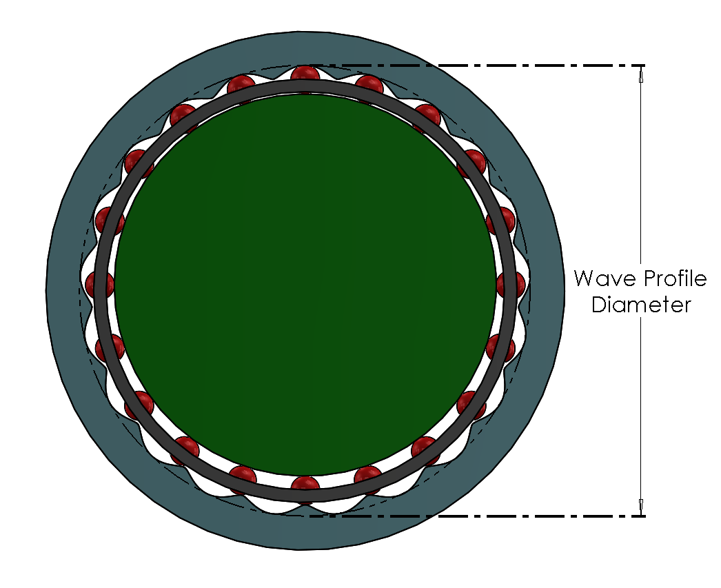
Wave Reducer Simulator with rolling elements are a class of speed reducers that transmit motion through a wave-like profile interacting with intermediate rolling elements, such as balls or rollers. Instead of using gear teeth like planetary or cycloidal drives, they rely on pure rolling contact to achieve high reduction ratios, low backlash, and compact size. The eccentric cam pushes the rolling elements against a specially shaped rigid ring, causing smooth, high-ratio relative motion between input and output.
Scroll to zoom. Drag to pan. Double-click to reset.
Status: Paused
Components to Display
Premium feature - access to the full app required
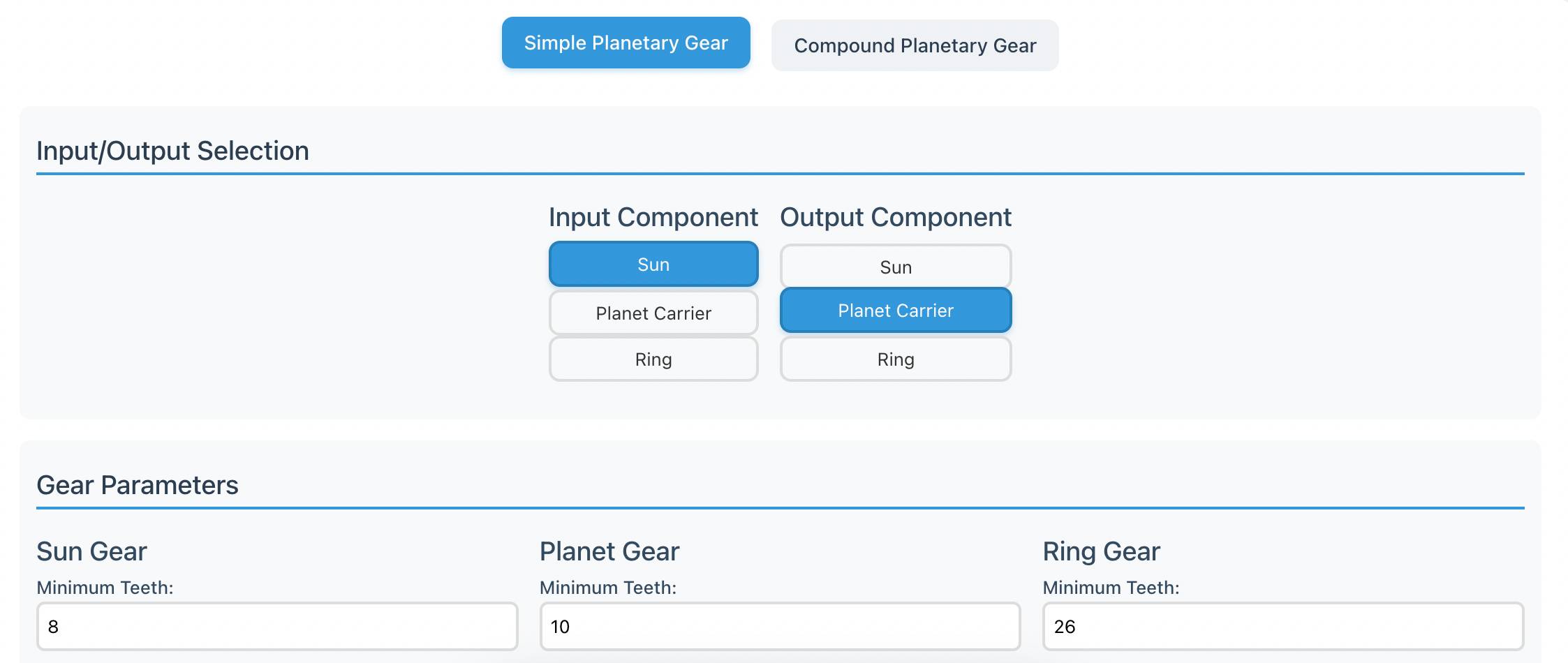
Configuration
InputEccentric Cam
OutputSeparator
Outputs
Gear Ratio20
Lobe Count19
Separator Thickness (mm)-
Wave Profile Diameter (mm)-?
?
Premium App access required to load saved configuration files.
?
Premium App access required to save calculator configurations.
Parameters
Pressure Angle vs Input Crank
This is a preview (not live) plot. Premium App access required for pressure angle plot.
Avg Pressure
Angle-
Range-
Contact Model
This calculator is adapted from: S. Fritsch, S. Landler, M. Otto, B. Vogel-Heuser, M. Zimmermann,
and K. Stahl,
“Static Modeling of the Stiffness and Contact Forces of Rolling Element Eccentric Drives for
Use in Robotic Drive Systems,”
in 2024 IEEE/RSJ International Conference on Intelligent Robots and Systems (IROS),
2024, pp. 3526-3533,
doi: 10.1109/IROS58592.2024.10802779.
Advanced Parameters
Preview plot shown. Premium App access required to calculate contact model changes.
Assumptions and Limitations
Purely Static Modeling
The Assumption: The model calculates forces and equilibrium positions
based strictly on static force balances.
The Limitation: Dynamic influences are completely ignored. The model
does not account for centrifugal forces at high rotational speeds, inertial loads during
acceleration, or external gravitational forces acting on the mechanism.
Rigid Body Constraints (Contact Deformation Only)
The Assumption: The stiffness of the drive is modeled entirely through
localized elastic Hertzian deformations at the contact points. The input shaft, output
shaft, and supporting bearings are treated as perfectly rigid.
The Limitation: Structural deformations outside of the contact zones are
neglected. Twisting of the input shaft, bending of the cage walls, and flexing of the
outer gear ring are not calculated. In reality, these macro-deformations will result in
a slightly lower overall system stiffness than the calculator predicts.
Linearization of the Ring Gear Contact at High Loads
The Assumption: For the rolling-element-to-ring-gear contact (Contact
C1) only, the relative indentation is linearized and a constant stiffness
parameter is assumed for each point on the gear profile. The other three contacts (crank
C2, cage C3 and C4) use the full nonlinear F =
Kδn form.
The Limitation: While this holds for small displacements, the source
paper explicitly states that this assumption becomes “increasingly inaccurate for
larger displacements.” The accuracy of the predicted twist and force curves
therefore decreases at the upper bounds of applied torque.
2D Planar Kinematics
The Assumption: All relevant displacements and internal forces are
assumed to occur purely in a two-dimensional plane orthogonal to the axis of rotation.
The Limitation: The model does not account for any 3D, out-of-plane
forces. Axial thrust, misalignment forces, and bending moments that naturally occur in a
physical robotic assembly are not reflected in the data.
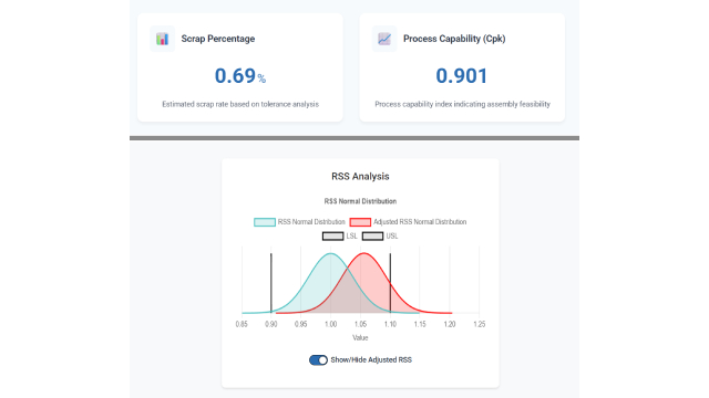
Statistical Independence and Normality of Tolerances
The Assumption: To generate the distribution curves (10th and 90th
percentiles), the Monte-Carlo simulation assumes that the manufacturing tolerances of
all individual parts and rolling elements are completely statistically independent.
Variations are sampled from normal distributions centered on the nominal dimension, with
the specified tolerance limits placed at ±3 standard deviations.
The Limitation: No systematic manufacturing errors are modeled. If a CNC
machine has a consistent tool deflection issue affecting an entire batch, or if parts
come from a bin-sorted process producing a skewed or truncated distribution, this model
will not accurately predict the real-world variance.
Undefined Maximum Torque Capacity
The Assumption: The simulation limits the range of twist based on the
internal contact pressures occurring within the system.
The Limitation: The math provides the forces at a given twist, but it
does not calculate the absolute failure point or the maximum permissible torque rating
of the drive. Users must independently cross-reference the generated contact forces
against the yield strength and fatigue life limits of their chosen materials.
No Experimental Validation
The Assumption: The underlying model relies on well-established
mechanical theory (Hertzian contact, methods adapted from cycloidal drives and roller
bearings) and comparisons to similar commercial drives, rather than direct experimental
measurement of a physical REE drive.
The Limitation: The source paper itself states: “Instead of
experimental validation, this work relies on well-established mechanical models,
state-of-the-art methods in related technologies, and comparisons to similar
drives.” Outputs of this calculator are model predictions, not measured behavior,
and should be treated accordingly when used for design decisions.
The Assumption: The Hertzian contact model assumes smooth elastic
contact between the rolling elements and their mating surfaces.
The Limitation: Friction, surface roughness, lubricant film effects,
plastic deformation, and hysteresis are not modeled. As a result, the calculator cannot
predict drive efficiency, heat generation, wear, or torque loss as a function of speed.
Linear Isotropic Material Behavior
The Assumption: All materials are treated as linear, isotropic, and
time-independent, characterized solely by Young's modulus and Poisson's ratio.
The Limitation: This assumption is especially weak for 3D-printed
plastic configurations. FFF/FDM parts are anisotropic (stiffness varies with print
direction), viscoelastic, and creep under sustained load. Predictions for plastic drives
should be treated as upper-bound estimates of stiffness.
Output Twist vs Output Torque
?
Predicts how much the output shaft will physically deflect, or wind up,
when a specific torque is applied. On this curve, the slope directly
indicates the drive's torsional stiffness.
How to use it?
Use it to predict how different materials or manufacturing tolerances
impact rigidity of the final drive.
Plot wiring pending
Force vs Input Twist
?
Predicts the max contact normal forces under elastic internal wind-up of
the input crank. Low stiffness drives will show lower contact forces
and higher material deformation, hence lower torque capacity. Inversely,
high stiffness drives will show high contact force, and less material
deformation results in higher torque output.
How to use it?
Use it to predict fatigue life, localized Hertzian contact stresses,
and stiffness.