


The four-bar linkage, often referred to as a four-bar mechanism, is a fundamental concept in mechanical engineering that plays a critical role in various machines and devices. From car suspensions to robotic arms, understanding the principles and applications of the four-bar mechanism is essential for engineers and designers. In this article, we’ll delve into the working principles, Grashof’s theorem, inversions, and applications and provide solved examples to enhance your understanding of this versatile mechanical linkage.
While reading about Four Bar Mechanisms is helpful for understanding the working principles, it is always more fun to get your hands dirty. For this reason, we have developed a basic 4-bar linkage Simulator, where you can see real-time animations of these fascinating devices. Check it out and let us know what you think; we are constantly working on adding new features and improving the user experience.

What is a Four-Bar Linkage?
A four-bar linkage, also known as a four-bar mechanism, is a mechanical linkage made up of four rigid bars or links joined by four joints or pivots. These joints allow for relative motion between the links, enabling regulated and predictable movements like rotation, translation, and oscillation. Four-bar linkages are commonly used in machinery, robotics, automotive systems, and other applications.
Let’s break down the terminology associated with a four-bar linkage:
Frame: The frame, often denoted as a fixed link (Link AB), is the link that remains stationary relative to the viewer.
Rocker: Any link that doesn’t revolve fully is referred to as a rocker (Link BC).
Crank: A crank (Link DA) is a link capable of rotating entirely.
Connecting Rod: The connecting rod or coupler (Link CD) connects the frame and the rocker.
Mathematically, a four-bar linkage can be described using various equations. The primary equation governing its motion is:
f(θ1,θ2,θ3,θ4)=0
Where:
θ1 and θ2 are the input and output angles of one of the bars.
θ3 and θ4 are the input and output angles of another bar.
This equation can be further elaborated upon to include link lengths and joint positions for more complex configurations.
Let’s delve into kinematics and introduce the concept of “degree of freedom” (DOF). For a four-bar linkage:
- Total links (l) = 4
- Joints (j) = 4
- Higher pairs (sliding joints) (h) = 0 (for planar mechanisms)
Using the Kutzbach criterion, which states “n = 3(l – 1) – 2j – h,” we calculate:
n = 3(4 – 1) – 2(4) – 0 = 1
This tells us that a four-bar linkage has one degree of freedom.
Grashof’s Theorem for Four-Bar Linkages
Grashof’s theory is essential for establishing whether or not a four-bar linkage may accomplish complete and unique motion. The total of the shortest and longest link lengths must be less than or equal to the sum of the other two link lengths for a four-bar connection to allow complete rotation, according to this theorem:
S + L ≤ P + Q
Examples of 4 Bar Mechanisms
Locking pliers, often known as Vise-Grips, are multipurpose tools that use a smart four-bar mechanism to achieve a secure and dependable grasp on a variety of items. This mechanism not only makes clamping easier, but it also assures that once clasped, the pliers retain their grasp without the need for constant manual force.
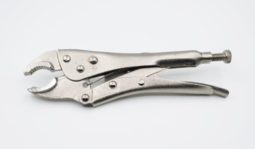
Locking Pliers in Real-Life Applications:
Automotive Repairs:
Locking pliers are commonly used in car repair and maintenance. They are used by mechanics to secure various components in place when conducting operations such as brake pad replacement, suspension work, or engine repairs. The locking mechanism maintains a tight grasp, allowing mechanics to work precisely and safely.
Woodworking:
Woodworkers use locking pliers When fastening pieces of wood during glue-ups or assembly. This keeps the wood parts firmly in place until the adhesive sets, resulting in solid and precise joins.
Plumbing:
Plumbers frequently use locking pliers to fasten pipes and fittings. These pliers can keep components in place while repairing or replacing pipes, preventing unwanted movement or leakage.
Metalworking:
Locking pliers are helpful in metalworking for holding metal components steady during cutting, welding, or shaping processes. They provide stability, lowering the danger of accidents and enhancing job quality.
Construction and Carpentry:
Construction workers and carpenters rely on locking pliers to keep items like beams, boards, or metal components in place while being put together. This ensures the precision and safety of construction projects.
Mechanical Advantage (MA) in Locking Pliers
Formula:
MA = Output Force / Input Force
Here’s the scoop:
- Output Force: This is how hard those locking pliers grip onto an object. Think of it as their “muscle.”
- Input Force: This is the power you put in when you squeeze the handles. Your effort.
Now, when you divide the output force by your effort, you get the MA. And here’s the kicker:
- High MA means less sweat: A big MA means those pliers are ultra-efficient. They turn your squeeze into a rock-solid grip, so you don’t have to break a sweat.
How’s it working? Your hand power multiplies at the jaws thanks to a clever four-bar linkage inside. So, you get a powerful grip without being a muscle champ. Cool, right?
Real-Life Applications of Four-Bar Mechanism in Bicycles
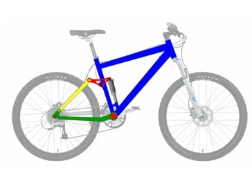
Pedaling Action: The pedaling action is the most evident application of a four-bar system in bicycles. When you press down on the pedals, the crankset rotates, transmitting power from your legs to the back wheel via the chain. This device converts your pedaling motion into the rotational motion of the wheel, propelling you ahead.
Gear Shifting: Bicycles employ a four-bar linkage to switch between gears. When you change gears, you’re essentially changing the effective lengths of the system’s four bars. This changes the mechanical advantage, allowing you to pedal at different speeds and tackle varied terrains, such as steep slopes and flat highways.
Rear Suspension Systems: A four-bar linkage is used in the rear suspension mechanism of some modern mountain bikes. When riding on rugged and uneven terrain, this system allows the back wheel to rotate independently of the main frame, offering superior traction and shock absorption.
Gear Ratio (GR): The gear ratio controls how many times the back wheel rotates for each pedal rotation. The number of teeth on the front chain ring (connected to the pedals) is compared to the number of teeth on the rear sprocket (attached to the wheel). A larger gear ratio allows you to cover more ground with every pedal rotation, which is perfect for faster speeds on flat terrain. A lower gear ratio provides more pedaling power, which is ideal for climbing hills.
Formula: Gear Ratio (GR) = Number of Teeth on Chainring / Number of Teeth on Rear Sprocket
Oil Well Pumps: Unlocking the Earth’s Liquid Gold
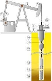
When you think of oil production, towering pump jacks in the middle of vast oil fields might come to mind. These giants are responsible for extracting “liquid gold” from deep within the Earth. What makes this possible is a mechanical marvel known as a reciprocating oil well pump powered by the simple yet efficient four-bar mechanism.
The Mechanism: The four-bar system within an oil well pump is essentially a clever seesaw. One end of the “seesaw” is attached to a rotating motor, while the other end is connected to a piston within the pump. This four-bar linkage expertly converts the engine’s constant circular motion into the rhythmic up-and-down motion required for oil pumping.
Formula: Imagine the piston inside the pump as a tiny superhero, constantly plunging into the depths of the well and returning with a load of precious oil. The amount of oil brought up with each stroke depends on two crucial factors: the piston’s cross-sectional area (A) and the distance it travels with each stroke (S). Engineers use a simple formula to determine this volume: Displacement (D) = A x S.
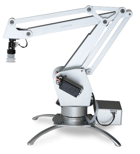
Robotic Arms: Precision in Motion

Robotic arms, the mechanical maestros of automation, often rely on four-bar linkages for their precision. These mechanical wonders deftly carry out tasks demanding pinpoint accuracy.
The Mechanism: Picture a robotic arm as a series of joints and links akin to a human arm. Four-bar linkages orchestrate their movements, allowing precise control over position and orientation. Motors drive these arms, while the four-bar linkage adjusts joint angles and positions. This finesse enables tasks from picking and placing to welding and painting.
The Mathematics: Behind these graceful moves lies inverse kinematics, the arm’s mathematical GPS. It calculates joint angles (θ) to reach target positions (x, y). The formula for inverse kinematics can be quite complex but generally involves the lengths of the links (a, b, c, d) and trigonometric functions to find these angles:
θ₁ = atan2(y, x) – atan2((d*sin(θ₂)), (a + d*cos(θ₂) – c))
θ₃ = acos((a + d*cos(θ₂) – c) / b) – θ₂
θ₄ = θ – θ₂ – θ₃
From intricate electronics assembly to delicate surgeries, robotic arms, with their concealed four-bar linkages and mathematical prowess, embody precision in motion, transforming industries and expanding horizons.
Pantographs: Powering Up the Road

Have you ever wondered how electric vehicles maintain their charge while in motion? The sleek mechanism known as the pantograph, a critical component in e-mobility, has the answer!
The Mechanism: Pantographs use an ingenious four-bar linkage technique to maintain continuous contact with overhead electricity wires. Consider it the vehicle’s electric umbilical cord. The pantograph’s arms extend and retract as the vehicle moves, ensuring the contact shoe remains connected to the power line and seamlessly transmits electricity for propulsion.
The Mathematics: Precision is essential in this tango between the vehicle and the electrical line. Geometry and trigonometry are used to determine the optimal proportions and angles for the pantograph’s arms. This is how it works:
– Let ‘L’ be the length of the pantograph arm.
– ‘θ₁’ represents the angle between the arm and the vehicle’s roof.
– ‘θ₂’ is the angle formed by the arm and the horizontal plane.
– ‘D’ stands for the distance between the arm’s pivot point and the power line.
– ‘H’ is the vertical distance from the power line to the arm’s pivot point.
Now, the formula for ‘L’ becomes:
L = D / sin(θ₂) + H / tan(θ₁)
These calculations ensure that the pantograph maintains precise contact with the power line as the vehicle moves, ensuring an uninterrupted flow of electricity to keep your electric ride going. Pantographs, with their mathematical precision and four-bar cleverness, are quietly powering future transportation.
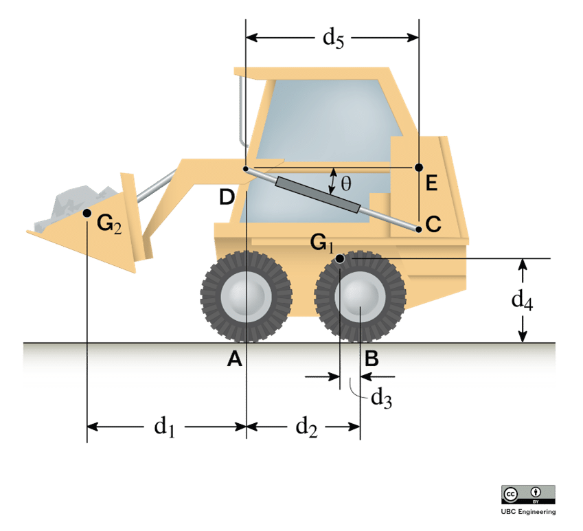
Loaders: Lifting the Weight of Construction

When it comes to heavy lifting on a construction site, loaders step into the spotlight. These robust machines owe their lifting prowess to a well-designed four-bar linkage mechanism, transforming them into the workhorses of the construction world.
The Mechanism: At the heart of a loader’s lifting power lies the four-bar linkage in its lifting arms. Like a superhero’s brawny limbs, these arms can hoist heavy items with accuracy and efficiency. The key is to change the lengths of the four bars. Operators can fine-tune the loader’s range of motion and lifting capacity to meet the job’s needs.
The Mathematics: Here’s where math flexes its muscles. Calculations involving the link lengths and angles determine how the loader behaves:
‘L₁’ represents the length of the loader’s main arm.
‘L₂’ is the length of the secondary arm.
‘L₃’ signifies the length of the bucket arm.
‘θ₁’ is the angle formed by the main arm.
‘θ₂’ represents the angle of the secondary arm.
These parameters, intertwined in a web of trigonometric equations, govern the loader’s lifting abilities. Adjusting ‘L₁’, ‘L₂’, or ‘L₃’ affects the machine’s reach and the weight it can effortlessly elevate, adapting it to various tasks on the construction site.
Wrapping it up
We’ve discovered the mechanical magic behind everyday comforts through our journey through real-life uses of four-bar connections. From locking pliers to oil well pumps, bicycles, robotic arms, and pantographs, these mathematically precise connections discreetly modify motion and improve our lives.
Next time you encounter a four-bar mechanism, from the subtle magic within your toolbox to the construction site’s powerful loader, remember these unsung heroes of motion. While they might not grab headlines, four-bar linkages are quietly at work, shaping the efficiency and convenience of our modern world. Keep an eye out for these mechanical wonders in your daily life, and you’ll have a newfound appreciation for their silent contributions.
Conclusion
Four-bar linkages, or four-bar mechanisms, are fundamental components in mechanical engineering with numerous practical applications. Understanding their principles, Grashof’s theorem, and various inversions is essential for designing machines, robots, and mechanisms that involve controlled motion. Whether you’re working on a complex industrial application or a simple educational model, the versatility of four-bar linkages makes them a valuable tool in the mechanical engineer’s toolkit.
Remember to check out our 4-bar linkage simulator to apply the principles discussed in this article
